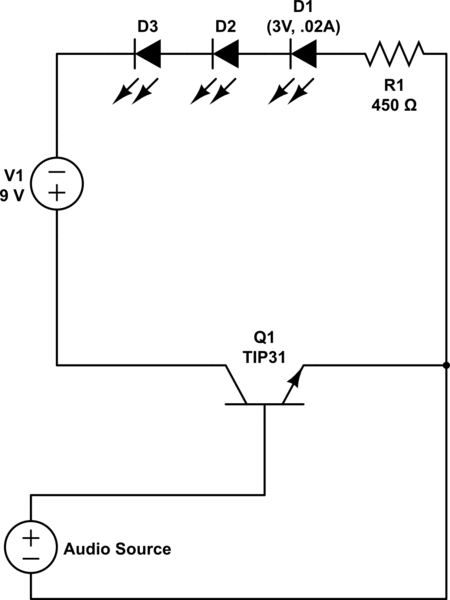
I have been charged with designing and making a circuit that makes LEDs brighten or dim to an audio source. The LED datasheet is KY59-TLHB4201 .At the time I thought I had a much greater understanding about electricity than I actually did. The questions and answers on this exchange have been instrumental in my coming to understand how it all really works, alongside the many useful and helpful links that people have posted in their answers.
After much searching, reading and experimenting, I feel I understand enough to ask a question or two of my own. Above is the schematic for my working circuit. I'm still trying to fine tune it and understand what my changes are doing, but that will have to wait until my parts can arrive in the mail.
In short, I have two questions about my design and the theory behind it.
First: How do I apply Kirchhoff's law of voltage to my circuit? Do I need to worry about Kirchhoff's law in my circuit? I understand that the total voltage drop across the circuit is supposed to reach 0 (9 volts in, 9 volts consumed), but I don't quite understand where the LED's fit into the equation. Obviously they're going to be applied as resistance, but there is no resistance rating on the packaging they came in. They're rated for 3V at .02A. If you plug those numbers into Ohm's law you get 150 Ohms of resistance, but if the LED had that much resistance I wouldn't need to put a resistor in front of it to keep it from having a much higher amperage and building up heat. Without knowing what resistance the LED's have (or how they consume voltage without that resistance) I'm left unsure of how to apply the law.
Second: Am I missing anything? I'm still new to the theory of all this and learning more every day, but my circuit 'works' to my eyes. I do understand that there could be quite a few things going wrong where I can't visually observe them, which is why I'm reaching out to the community. I've seen circuits that use capacitors somewhere between the LEDs and the audio signal. I understand this has to do with analog wave forms, but my understanding stops about there. I also lack the tools to test and see if the wave form coming out of my audio source (my phone) is an actual analog wave or a digital wave.
If you see something else wrong with my circuit, please feel free to point it out and explain or link me to a page that explains it (or both, I like both). Any and all help will be greatly appreciated.
Since my knowledge of this subject is entirely self tought (my formal learning is all on the software side of things!), "here, go read this" is a perfectly acceptable reply!


